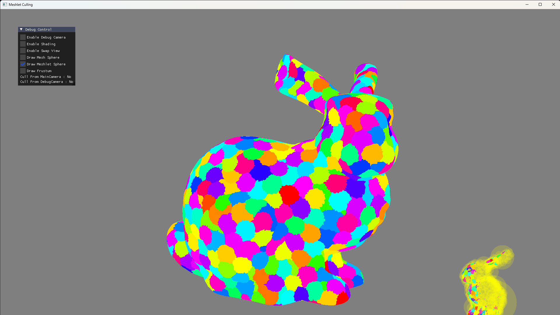
2025年のCEDECで発表した内容のサンプルプログラムをそういや公開していないなぁと思ったので,今回はCEDECで話した内容のうち下記についてのサンプルプログラムを公開しようかなと思います。
メッシュレット単位のカリング
ポリゴン単位のカリング
まずは,視錐台カリング(View Frustum Culling)です。これはカメラの描画範囲に入らないオブジェクトをカリングする手法です。カメラのビューボリュームを構成する6平面との距離を求め,ビューボリューム内に収まっていれば描画,範囲外なら描画対象から外せばよいです。
バウンディングスフィアで実装する場合は基本的には平面との符号付き距離を求めればよいだけなので,内積命令を呼び出せばよいという実装もお手軽な手法です。実装は下図のようになります。
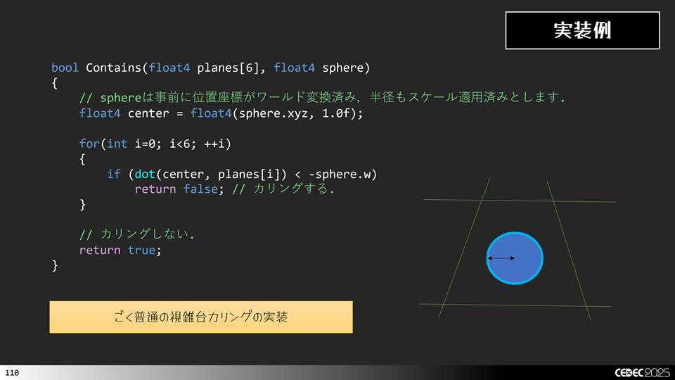
あとは,これを増幅シェーダから呼び出すようにすればよいです。
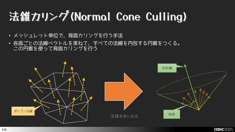
法錐の求め方にはいくつありますが,meshOptimizerを使うと簡単に実装できます。ここではmeshOptimizerのmeshopt_computeMeshletBounds()関数を使って法錐を求めてみます。
//-----------------------------------------------------------------------------
// メッシュレット生成を行います.
//-----------------------------------------------------------------------------
bool CreateMeshlets(const char* path, ResMeshlets& result)
{
MeshOBJ mesh;
if (!mesh.Load(path))
{
ELOGA("Error : MeshOBJ::Load() Filed. path = %s", path);
return false;
}
auto& indices = mesh.GetIndices ();
auto& positions = mesh.GetPositions();
auto& normals = mesh.GetNormals ();
auto& texcoords = mesh.GetTexCoords();
auto& tangents = mesh.GetTangents ();
const size_t kMaxVertices = 256;
const size_t kMaxTriangles = 256;
const float kConeWeight = 0.0f;
uint64_t meshletOffset = 0;
for(const auto& subset : mesh.GetSubsets())
{
auto maxMeshlets = meshopt_buildMeshletsBound(subset.Count, kMaxVertices, kMaxTriangles);
std::vector<meshopt_Meshlet> meshlets (maxMeshlets);
std::vector<uint32_t> meshletVertices (maxMeshlets * kMaxVertices);
std::vector<uint8_t> meshletTriangles(maxMeshlets * kMaxTriangles * 3);
auto meshletCount = meshopt_buildMeshlets(
meshlets.data(),
meshletVertices.data(),
meshletTriangles.data(),
&indices[subset.Offset],
subset.Count,
&positions[0].x,
positions.size(),
sizeof(asdx::Vector3),
kMaxVertices,
kMaxTriangles,
kConeWeight
);
meshlets.resize(meshletCount);
for(auto& meshlet : meshlets)
{
meshopt_optimizeMeshlet(
&meshletVertices [meshlet.vertex_offset],
&meshletTriangles[meshlet.triangle_offset],
meshlet.triangle_count,
meshlet.vertex_count);
auto primOffset = uint32_t(result.Primitives.size());
auto vertOffset = uint32_t(result.VertexIndices.size());
for(auto i=0u; i<meshlet.vertex_count; ++i)
{
auto vertIndex = meshletVertices[i + meshlet.vertex_offset];
result.VertexIndices.emplace_back(vertIndex);
}
for(auto i=0u; i<meshlet.triangle_count * 3; i+= 3)
{
uint8_t3 tris = {};
tris.x = meshletTriangles[i + 0 + meshlet.triangle_offset];
tris.y = meshletTriangles[i + 1 + meshlet.triangle_offset];
tris.z = meshletTriangles[i + 2 + meshlet.triangle_offset];
result.Primitives.emplace_back(tris);
}
MeshletInfo m = {};
m.VertexOffset = vertOffset;//meshlet.vertex_offset;
m.VertexCount = meshlet.vertex_count;
m.PrimitiveOffset = primOffset;//meshlet.triangle_offset;
m.PrimitiveCount = meshlet.triangle_count;
auto bounds = meshopt_computeMeshletBounds(
&meshletVertices[meshlet.vertex_offset],
&meshletTriangles[meshlet.triangle_offset],
meshlet.triangle_count,
&positions[0].x,
positions.size(),
sizeof(asdx::Vector3));
auto normalCone = asdx::Vector4(
asdx::Saturate(bounds.cone_axis[0] * 0.5f + 0.5f),
asdx::Saturate(bounds.cone_axis[1] * 0.5f + 0.5f),
asdx::Saturate(bounds.cone_axis[2] * 0.5f + 0.5f),
asdx::Saturate(bounds.cone_cutoff * 0.5f + 0.5f));
m.NormalCone.x = uint8_t(normalCone.x * 255.0f);
m.NormalCone.y = uint8_t(normalCone.y * 255.0f);
m.NormalCone.z = uint8_t(normalCone.z * 255.0f);
m.NormalCone.w = uint8_t(normalCone.w * 255.0f);
m.BoundingSphere.x = bounds.center[0];
m.BoundingSphere.y = bounds.center[1];
m.BoundingSphere.z = bounds.center[2];
m.BoundingSphere.w = bounds.radius;
result.Meshlets.emplace_back(m);
}
ResSubset subsets = {};
subsets.MaterialId = subset.MaterialId;
subsets.MeshletOffset = meshletOffset;
subsets.MeshletCount = meshletCount;
result.Subsets.emplace_back(subsets);
meshletOffset += meshletCount;
}
result.Positions = positions;
result.Normals = normals;
result.Tangents = tangents;
result.TexCoords = texcoords;
result.VertexIndices.shrink_to_fit();
result.Primitives .shrink_to_fit();
result.Meshlets .shrink_to_fit();
result.Subsets .shrink_to_fit();
{
auto bounds = meshopt_computeSphereBounds(
&result.Positions[0].x,
result.Positions.size(),
sizeof(asdx::Vector3),
nullptr,
0);
result.BoundingSphere = asdx::Vector4(
bounds.center[0],
bounds.center[1],
bounds.center[2],
bounds.radius);
}
return true;
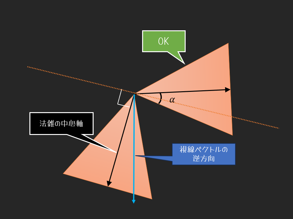
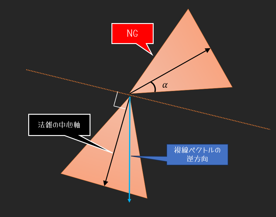
}これで,法錐が求まりましたので、実際にカリングを考えます。 まずカリングできないケース(描画がOKなケース)から。背面カリングは法線が後ろ側,つまり90度以上になっているケースでカリングします。これを法錐にあてはめます。中心軸が90度以上になっていても,下図のようなケースではカリングしてはいけません。法錐の一部が90度よりも手前に来るケースがあるからです。
続いて、カリングできるケース(描画NGなケース)を考えます。先程の図からわかるように,法錐全体の範囲が90度以上でないとだめですので,下図のようなケースでは,カリングできます。
これらの例から法錐カリングできる条件は下記のように定まります。NG領域に入っているものをカリングします。
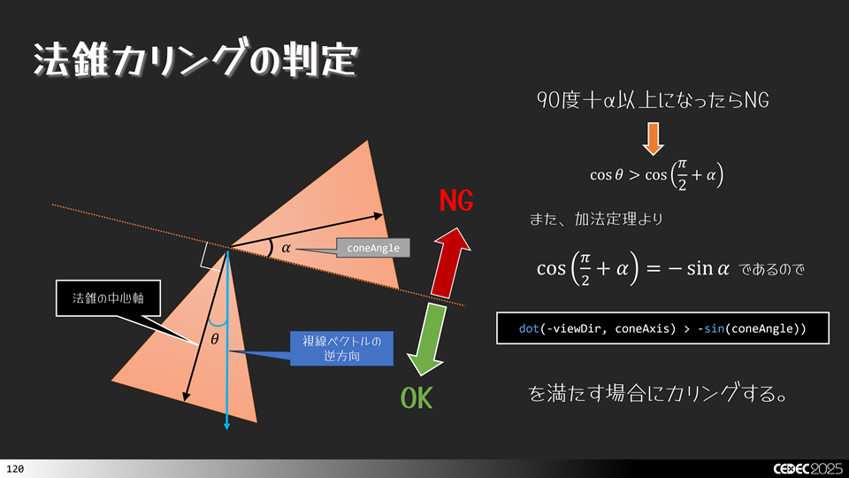
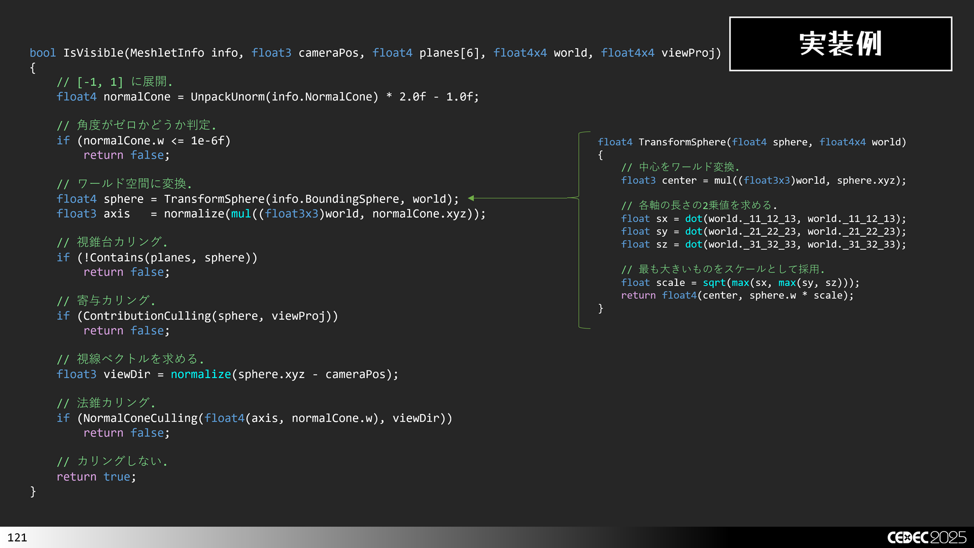
これを実際のコードに落とし込むと,下図のようになります。
続いて、寄与カリング(Contribution Culling)です。メッシュレットが小さすぎてピクセルに寄与しない場合にカリングする手法です。カメラから遠く離れているオブジェクトやシャドウマップに描画する際に効果がある手法です。カメラに近い場合は条件に該当しないケースが大半となるので,カリング処理の分だけ無駄計算を行うことになってしまい返って遅くなるので,注意してください。
実装としては,スクリーンに投影したバウンディングボリュームのx成分とy成分の長さを求めて,指定閾値未満ならカリングを実行します。例えば,1ピクセルに満たないならカリングするといった感じです。
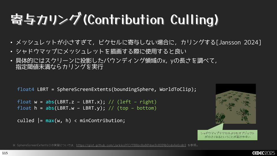
まずは,スクリーンに投影したバウンディングボリュームの領域を調べる必要があります。これは,SphereScreenExtents()という関数で求めます。この関数の実装は次のような感じです。
//-----------------------------------------------------------------------------
//      スクリーン上の矩形を求めます.
//-----------------------------------------------------------------------------
float4 SphereScreenExtents(float4 sphere, float4x4 viewProj)
{
    // https://gist.github.com/JarkkoPFC/1186bc8a861dae3c8339b0cda4e6cdb3
    float4 result;
    float r2 = sphere.w * sphere.w;
    float d  = sphere.z * sphere.w;

    float hv = sqrt(sphere.x * sphere.x + sphere.z * sphere.z - r2);
    float ha = sphere.x * hv;
    float hb = sphere.x * sphere.w;
    float hc = sphere.z * hv;
    result.x = (ha - d) * viewProj._11 / (hc + hb); // left
    result.z = (ha + d) * viewProj._11 / (hc - hb); // right

    float vv = sqrt(sphere.y * sphere.y + sphere.z * sphere.z - r2);
    float va = sphere.y * vv;
    float vb = sphere.y * sphere.w;
    float vc = sphere.z * vv;
    result.y = (va - d) * viewProj._22 / (vc + vb); // bottom
    result.w = (va + d) * viewProj._22 / (vc - vb); // top.

    return result;
}
あとは,この関数でleft, right, top, bottomの位置が求まるので,引き算して長さを求めればよいです。そのため, 図XX に示したような実装になります。
次にポリゴン単位のカリングの話に移ります。
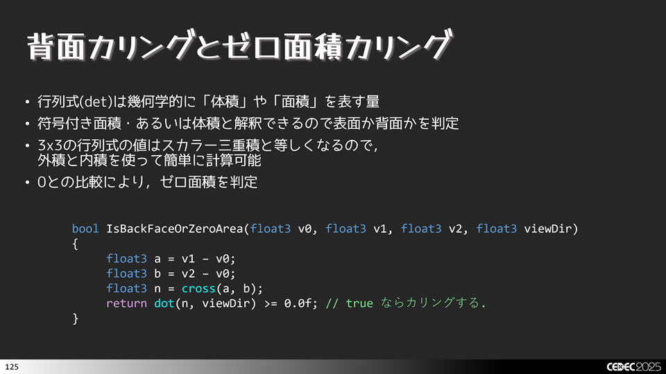
先程はメッシュレット単位でカリングしましたが,これにポリゴン単位のカリングを加えてさらに効率化を図ります。最初は背面カリングとゼロ面積カリングです。こちらは,裏面かどうかを判定してカリングすればよいです。3x3の行列式を使うと符号付き面積が求まり,表面か裏面かどうかを判定することができます。ここで線形代数の知識を使うと,3x3の行列式の値は,スカラー三重積(Scalar Triple Product)と等しくなるので,外積と内積を使うと比較的簡単に実装できます。
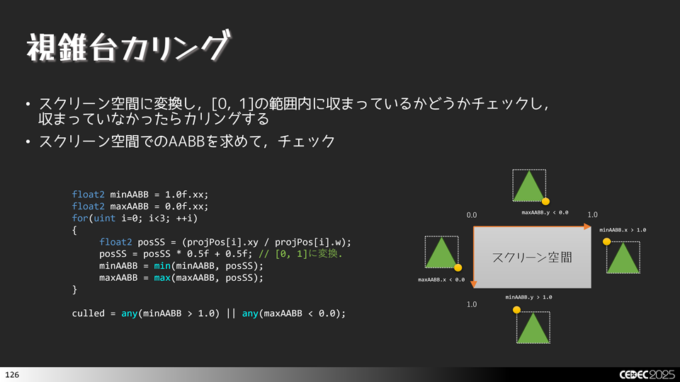
続いて、ポリゴン単位の視錐台カリングです。特に巨大なオブジェクトなどはメッシュレット単位ではカリングされないけど,ポリゴン単位でははみ出ているものがあるので,こうした無駄なものをカリングするのに適しています。実装として,射影空間に変換した後の位置座標をw成分で除算し,[0, 1]の範囲のスクリーン空間に変換し,0~1に収まっていないものをカリングすればよいです。
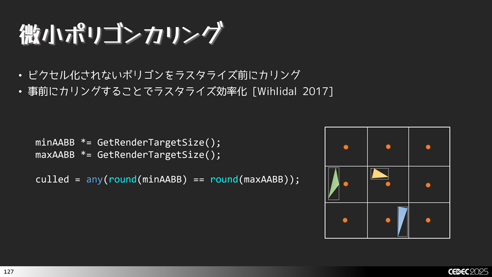
続いては,微小ポリゴンカリングです。メッシュレットやっていた寄与カリングと同じ考え方です。ピクセル化されなポリゴンを事前にカリングし,無駄にラスタライザーに渡さないようにします。こうすることで効率化が図れます。実装としてビューポート空間(あるいはウィンドウサイズ空間)でのAABB(Axis Aligned Bounding Box)を求めて,整数に丸め込めた値が,一緒であれば点となるので,この場合にカリングします。
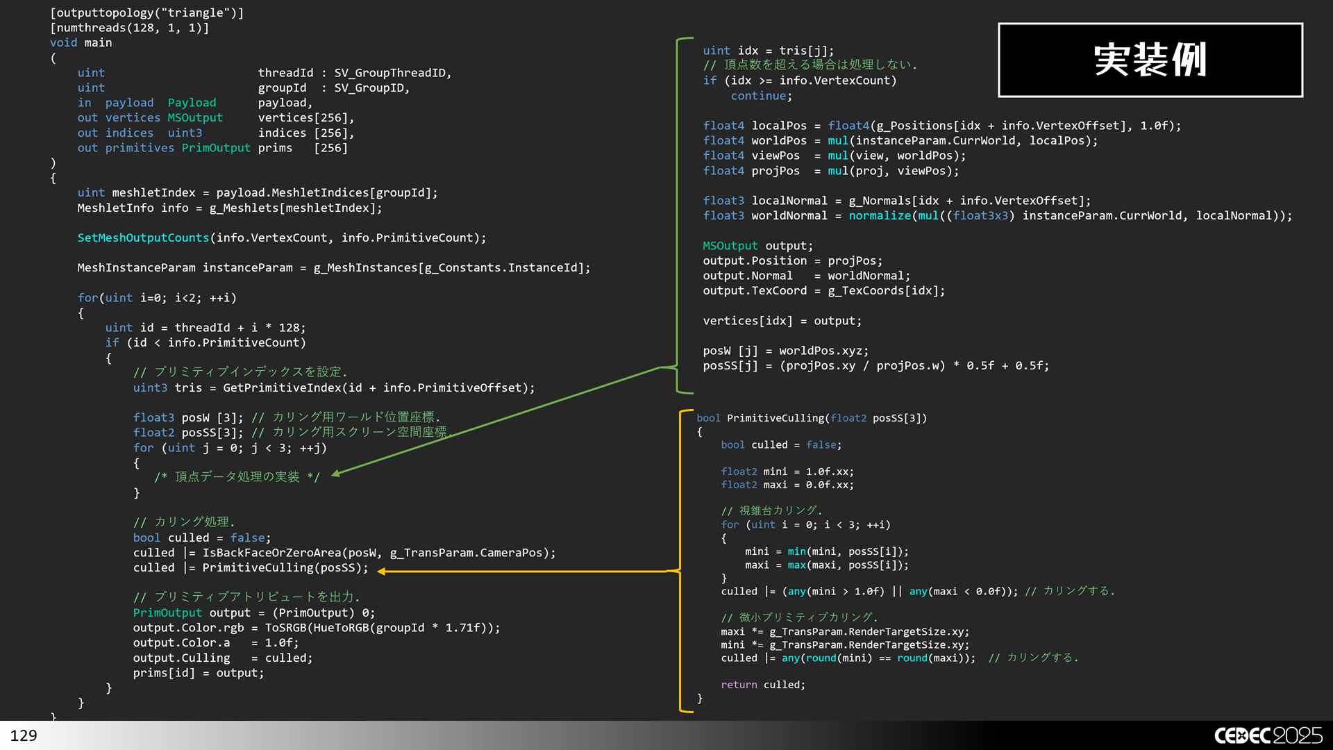
ここまで紹介したポリゴン単位のカリングの実装例は次のような感じになります。
//-----------------------------------------------------------------------------
//      背面カリングとゼロ面積カリング.
//-----------------------------------------------------------------------------
bool IsBackFaceOrZeroArea(float3 worldPos[3], float3 cameraPos)
{
    float3 viewDir = normalize(cameraPos - worldPos[0]);

    float3 a = worldPos[1].xyz - worldPos[0].xyz;
    float3 b = worldPos[2].xyz - worldPos[0].xyz;
    float3 n = cross(a, b);
    return dot(n, viewDir) >= 0.0f; // カリングする.
}

//-----------------------------------------------------------------------------
//      視錐台カリングと微小プリミティブカリング.
//-----------------------------------------------------------------------------
bool PrimitiveCulling(float2 posSS[3])
{
    bool culled = false;

    float2 mini = 1.0f.xx;
    float2 maxi = 0.0f.xx;

    // 視錐台カリング.
    for (uint i = 0; i < 3; ++i)
    {
        mini = min(mini, posSS[i]);
        maxi = max(maxi, posSS[i]);
    }
    culled |= (any(mini > 1.0f) || any(maxi < 0.0f)); // カリングする.

    // 微小プリミティブカリング.
    maxi *= g_TransParam.RenderTargetSize.xy;
    mini *= g_TransParam.RenderTargetSize.xy;
    culled |= any(round(mini) == round(maxi));  // カリングする.

    return culled;
}


//-----------------------------------------------------------------------------
//      メインエントリーポイントです.
//-----------------------------------------------------------------------------
[outputtopology("triangle")]
[numthreads(128, 1, 1)]
void main
(
    uint                      threadId : SV_GroupThreadID,
    uint                      groupId  : SV_GroupID,
    in  payload  Payload      payload,
    out vertices MSOutput     vertices[256],
    out indices  uint3        indices [256],
    out primitives PrimOutput prims   [256]
)
{
    // メッシュレット情報を取得.
    uint meshletIndex = payload.MeshletIndices[groupId];
    MeshletInfo info = g_Meshlets[meshletIndex];

    // 出力頂点数とインデックス数を設定.
    SetMeshOutputCounts(info.VertexCount, info.PrimitiveCount);

    // メッシュインスタンスパラメータを取得.
    MeshInstanceParam instanceParam = g_MeshInstances[g_Constants.InstanceId];

    float4x4 view;
    float4x4 proj;

    if (!!(g_Constants.Flags & 0x1))
    {
        view = g_TransParam.DebugView;
        proj = g_TransParam.DebugProj;
    }
    else
    {
        view = g_TransParam.View;
        proj = g_TransParam.Proj;
    }

    // インデックス数以内の場合.
    for(uint i=0; i<2; ++i)
    {
        uint id = threadId + i * 128;

        if (id < info.PrimitiveCount)
        {
            // プリミティブインデックスを設定.
        #if 1
            uint3 tris = GetPrimitiveIndex(id + info.PrimitiveOffset);
        #else
            uint3 tris = UnpackPrimitiveIndex(g_Primitives2[id + info.PrimitiveOffset]);
        #endif
            indices[id] = tris;

            // カリング用.
            float3 posW [3];
            float2 posSS[3];

            for (uint j = 0; j < 3; ++j)
            {
                uint idx = tris[j];
                // 頂点数を超える場合は処理しない.
                if (idx >= info.VertexCount)
                    continue;

                uint vertId = g_VertexIndices[idx + info.VertexOffset];

                float4 localPos = float4(g_Positions[vertId], 1.0f);
                float4 worldPos = mul(instanceParam.CurrWorld, localPos);
                float4 viewPos  = mul(view, worldPos);
                float4 projPos  = mul(proj, viewPos);

                float3 localNormal = g_Normals[vertId];
                float3 worldNormal = normalize(mul((float3x3) instanceParam.CurrWorld, localNormal));

                MSOutput output;
                output.Position = projPos;
                output.Normal   = worldNormal;
                output.TexCoord = g_TexCoords[vertId];

                vertices[idx] = output;

                posW [j] = worldPos.xyz;
                posSS[j] = (projPos.xy / projPos.w) * 0.5f + 0.5f;
            }

            // カリング
            bool culled = false;
            culled |= IsBackFaceOrZeroArea(posW, g_TransParam.CameraPos);
            culled |= PrimitiveCulling(posSS);

            // プリミティブアトリビュートを出力.
            PrimOutput output = (PrimOutput) 0;
            output.Color.rgb = ToSRGB(HueToRGB(meshletIndex * 1.71f));
            output.Color.a   = 1.0f;
            output.Culling   = culled;
            prims[id] = output;
        }
    }
}今回は,CEDEC 2025で発表した内容の一部のサンプルプログラムを公開してみました。やっぱり人前に見せるとなると,ちゃんとコード整理とかしないといけないので,ついつい億劫になってしまいます。もし、不具合があればご報告頂けるとありがたいです。
本ソースコードおよびプログラムはMITライセンスに準じます。
プログラムの作成にはWindows 11, およびMicrosoft Visual Studio 2026 Communityを用いています。